During 1930 construction commenced on a 3ft 6in gauge line from Pepel to Marampa in the northern province of Sierra Leone. Pepel is a private port on the Sierra Leone River, some fifteen miles from Freetown. Marampa is the home of a large haematite iron ore deposit some eighty miles north-east of Freetown. The line was constructed by the Sierra Leone Development Company - this railway was not connected to any of the other rail lines in Sierra Leone.
Total length of the line was fifty two miles, with an axle loading of thirteen tons. Trains were organised to haul thirty bogie wagons with each wagon capable of carrying thirty tons of ore. The line was laid with 65lb rail with a maximum gradient of 1 in 125 for the loaded westbound trains and 1 in 57 for the eastbound empties. Maximum altitude on the line was only 190 feet.
When the line opened in 1933 two 151 ton 2-8-2 + 2-8-2 Beyer-Garratt locomotives handled the ore trains, two more were recieved, one in 1935, the other in 1936.
The BRCW Diesels
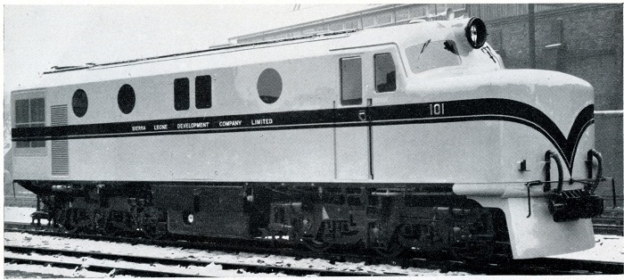
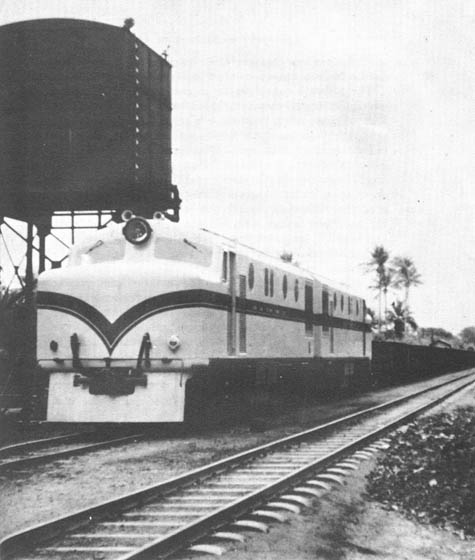
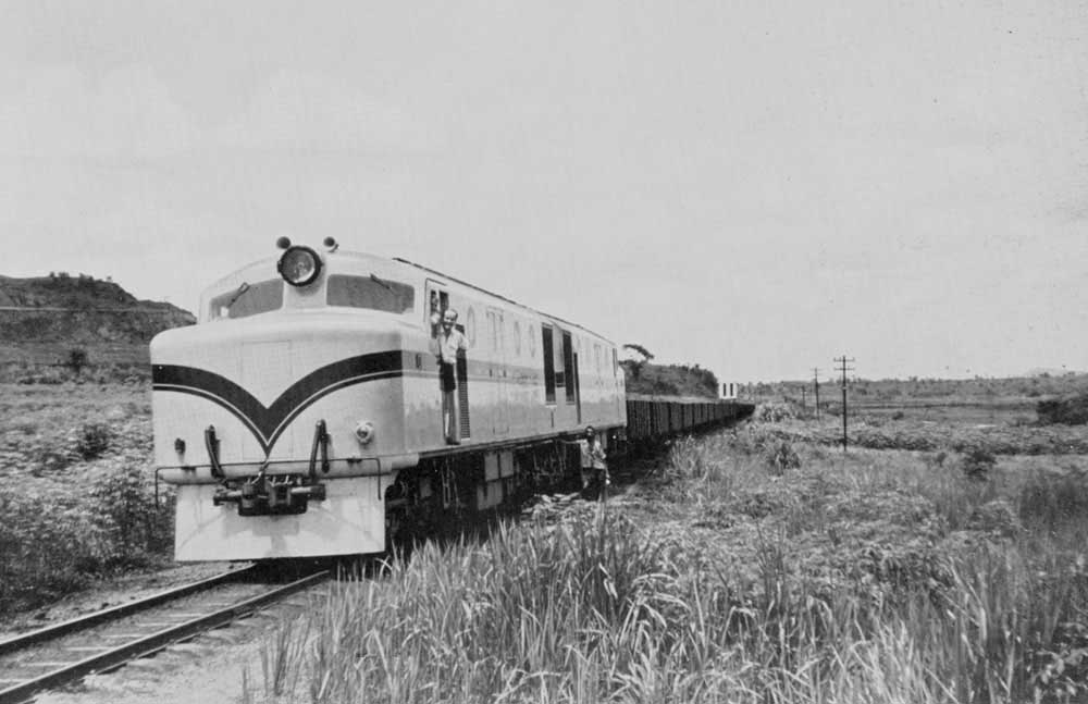
During the early part of 1955 five locomotives were delivered from the Birmingham Railway Carriage & Wagon Co Ltd (BRCW) workshops at Smethwick to Sierra Leone. The power unit was supplied by Sulzer Bros (London) Ltd and the electrical equipment by Crompton Parkinson Ltd. The locomotives were for use by the Sierra Leone Development Company and were designed and built to the requirements, supervision & inspection of Messrs Livesey & Henderson, consulting engineers to the SLDC.
The power unit was a pressure charged Sulzer 6LDA28 developing a continuous 1,000hp at 710rpm using six 280mm by 360mm (11in by 14.2in) cylinders. For its use in Sierra Leone the rating was reduced to 850hp at 710rpm. Dry weight of the engine including underbed and mounted accessories was 20,000lb. Tests on a similar power unit had produced 1,300hp at 750rpm with a clear exhaust. The well tried design featured a welded mild steel crankcase with cast steel transversals welded in, and with crankcase side prolongations to form the common underbed for the engine & generator. Laterally the crankcase is reinforced by U-shaped main bearing saddles with top caps let into the crankcase structure to act as bridge pieces, avoiding the use of studs.
Water & oil were cooled in two Serck side mounted radiators, air being drawn through by an electrically driven Davidson fan, the air expelled through the roof. The fan motor was connected to the motor of the traction motor blower group, both running at reduced speed until notch 5 was reached. Ducting for the cooling air was aluminium, each radiator assembly was removeable as a whole unit. The cooling water pump was electrically powered, starting up with the main engine, but continuing to run after engine shut down until stopped by the driver.
The engine room was pressurised using two Davidson fans, drawing air through side grilles and downwards into a filter cabinet. This would remove the larger dust particles, large banks of Visco oil-wetted air filters would captured the remainder of the dust prior to the air entering the engine room. Two traps in the roof allow for hot engine air to escape upward, though these traps may be closed in severe dust conditions.
The Crompton Parkinson main & auxiliary generators were carried on the common underbed. They were combined on a common rotor of cast steel 'bottle' form, providing a high stiffness/weight ratio. The generator coupling was also integral with the main/auxiliary rotor, a space saving which did not compromise accessibility to these components. The whole generator assembly is a single bearing machine with a parallel roller bearing at the outer end. The bearing is carried in a removeable cartridge, allowing for easy examination without disturbing the end shield which is also the auxiliary generator magnet frame. Hand barring gear is fitted in the inner end of the main rotor for turning the whole engine/generator assembly.
The main generator was a ten pole machine with a continuous rating at 535kW at 710rpm 535V. 1,000amp. The rating of the eight pole auxiliary generatoe was 63kW at 500-710rpm 100V 575 amp. Voltage was maintained constant by a Brown Boveri regulator mounted on the l.t. cubicle. Four Crompton Parkinson force ventilated nose-suspended traction motors were rated at 197hp 300amp 550V one hour, or 165hp 250amp 550V continuous. They drive through single reduction gears of 14:65 ratio. They have plain axle suspension bearings with pad & wick lubrication. Control gear was designed and manufactured by Allen West & Co Ltd. The main control gear is housed in a cubicle near the main generator, control gear for the auxiliary generator is housed at the other end of the locomotive. Both housings are dust proofed. The main motor contactor group and the reverser are electro-pneumatically operated, the weak field contactors and all auxiliary contactors are electro-magnetic. Weakening of the traction motor fields is effected automatically in three stages.

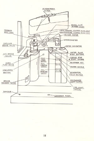
The underframe & body framing are completely welded structures in themselves but are riveted to each other. Double sheathing with outer panels of steel and inner panels of aluminium with Isoflex insulation between was applied to the cab sides and front, the steel bulkhead had asbestos insulation. All controls not deemed essential in driving the locomotive are positioned away from the cab in lockeable cabinets, accessible only to authorised personel. In light of the extreme condensation encoutered windscreen wipers are fitted on both sides of the glass. Fuel and batteries were positioned on the underframe between the bogies. The main tank held 665 gallons, supplying a 50 gallon auxiliary tank in the engine room. The nife nickel-cadmium batteries are mounted on sliding rails either side of the fuel tank.
The fully welded bogie frames are stress relieved as single units. The main members of the bogie are box shaped, utilising the open box form to allow the side members of the frame to accomodate the equalisers. All vertical loads, traction & braking stresses are taken centrally and all in line on the main frame members of the bogie. Nests of helical springs form the complete suspension between between the equalisers and the bogie frame. The springs are supplemented by shock absorbers which act only on their return stroke. Side movements of the swinglinks are controlled by rubber springs. The Timken roller-bearing axleboxes have thrust faces of manganese steel bearing against liners of the same material.
Westinghouse straight air brakes are fitted to the locomotive with vacuum equipment for the train brakes. There are two blocks to each wheel and four air cylinders per bogie. Sulzer's patent anti-slip brake is fitted to the locomotive to facilitate starting under poor conditions and comes into use automatically whenever the air sanders are used.
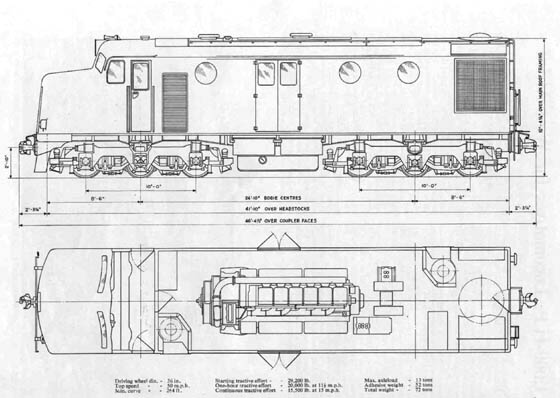
Two diesels were operated back to back in multiple on trains of forty double bogie ore wagons of thirty tons carrying capacity. With the line limited to a top speed of 28mph, a round trip would take about five hours to complete, not including any time taken at the termini. During the mid 1960's improvements to the track allowed the axle loading to increase to 16 tons, with the maximum speed increased to 35mph. New roller bearing equipped wagons had an increased capacity of fifty tons.
![]()
1974/1975
The following note comes from Dennis Haughey (January 2005)
Hello, I was really fascinated to find on your site an article about the railway from Pepel to Marampa in Sierra Leone. During the period 74/75 I was in charge of the the workshop on Pepel Island. I was there with my wife and two young children and it was a bit like living in paradise.
Even then the Sulzers were a bit tired, ( we also tyred them ) They were in more or less constant use but we had one ALCO when I arrived and took delivery of one whilst I was there and we began to rely heavily on these. Unfortunatly we put tyres on one of the ALCOs.....It made a light run to Marampa okay and back to the passing place, (forget the name of the little station), but in attempting to pull away all the tyres came off!
Talk about steep learning curves for an ex marine engineer, that was a real mess to sort out seeing as our heaviest tools were 25 ton Tangy jacks.
The first Alco to arrive at the SDLC was numbered 201 during 1964 (Alco b/n 3377.01), with Co-Co wheel arrangement).
Three more arrived during 1970 numbered 202 - 204, now built by the Montreal Locomotive Works (M6039.01-03, model # DLK543). No doubt these locomotives were responsible for the gradual run down of the BRCW's.
Dennis also advises that somewhere in the undergrowth was a very modern (for the 1970's) Badish lining, levelling and tamping machine that the permanent way gang spent a year attempting to commission. They were not successful and reverted to the more normal equipment used by the gangers - little rail cars powered by Ford 105e engines. Taking a ride on one of these cars was deemed quite an experience.
Additionally, a short walk from the rail shed was a power station whose output was used to power the iron ore conveyors and reclaimer systems. The engines used were horizontal low speed Crossleys.
![]()
1997
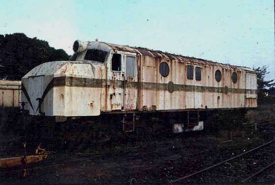
Despite the failing light on February 1st 1997 John was able to capture 104 on film in the very twilight of its life. Forty two years have gone by since delivery from Birmingham, the shiny paint is long gone and 104 is now reduced to the status of a tool shed, the body shell is completely gutted. What happened to the original nose yet remains to be answered.
John adds:
"104 was at Pepel Island standing outside the Locomotive depot where there were also two EE 0-6-0DH (one is just visible behind 104) and four ALCO's. The ore wagons and a Smith Rodley crane dating from the opening of the line were also here. Although the line had not operated for some years there were still sixteen staff present including a foreman who had been on the line since 1955. The whole lot was being maintained on a care and maintenance basis for who knows what. Whether this lot has survived the latest round of civil unrest is anyone's guess (although its so remote and isolated that I would guess its all still intact). The foreman stated that everything else on the 3'6" gauge line had been scrapped although some narrow gauge equipment remained at the mine which was inaccessible except by helicopter, (the mine had 2'0" gauge RH & OK diesels).
The main line track from Pepel to the mine is intact although completely overgrown with trees and completely impassable. The bridge over to Pepel Island is the only usable piece of line (about 300 yards) which has a 4-wheel flat wagon pushed by hand which is the only way the reach the shed and port, there is no road access. To get to the bridge involves some real bundu bashing down a four wheel drive track through the jungle. You have to go with someone who knows the way ! Once you get to the shed the staff keep the shed yard reasonably tidy and even stated that they started up one of the ALCO's once a month or so to keep it in working order, one of the EE's also appeared to be in working order. The depot is a very well equipped workshop".
![]()
Update January 2005
The following information & pictures comes from a correspondent who visited Pepel during December 2004.
As can be seen from the views the state of the equipment at Pepel varies from derelict to serviceable. The line north east from Pepel is intact but overgrown most everywhere. It is presumed that the internal civil unrest which has been endured by Sierra Leone for the past two decades did not cause much damage to the infrastructure due to its remote location.
There is now a great interest in the bauxite deposits near Port Loko, which ironically sits astride the former SLDC Pepel - Marampa iron ore line. So it is conceivable that the line and the ship loading facilities may once again see activity.
 |
As mentioned in John's text above the access to Pepel is via a bridge, the method of propulsion seen here. Note the mixed wood and metal sleepers. |
 |
Shunter 151, lettered for 'Marampa Mines' stands outside the facility, to the left is the last 'intact' BRCW diesel electric - now in use as a tool shed. |
 |
Inside the facility missing both bogies is 204, which seems like it could be put back into service with a minimum of work! |
 |
The state of the railway near Rogberi Junction. |


